What is the best way to operate hole openers?
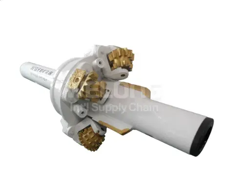
A hole opener is used to open an already drilled pilot hole to a bigger diameter. It is utilised extensively in top-hole portions, conductor and surface casing runs, and horizontal directional drilling crossings. Screwing it on the string and twisting the rotary is more to running one properly. Good location, proper drilling parameters, good circulation, careful observation of torque and vibration and step-by-step work for extremely big holes all provide the greatest results. This article examines each of these procedures so that drilling teams may have a smooth, full-gauge hole, greater cutter life and fewer unscheduled excursions.
How Should a Hole Opener Be Positioned Behind the Pilot Hole?
Using a Pilot Bit or Bull Nose for Guidance
A hole opener works best when something in front of it keeps it centred. Many operators run a pilot bit under the tool, drilling and enlarging in one pass. Others utilise a guide sub or bull nose once the pilot hole has been bored. Whichever way the leading section is angled, it follows the existing hole, so the cutter arms contact the formation uniformly and do not stray off the intended path.
Matching Pilot Hole Size to the Opening Ratio
The difference between the pilot diameter and the final diameter dictates how much rock each cutter has to remove. If the step is too big, a hole opener bears unequal loads, vibrates more and wears its cutters out rapidly. Most drill programs remain within the manufacturer’s specified range for expansion ratio. If the target diameter is significantly greater, the task is broken up over a number of passes and this is discussed further in the article.
Stabilization in the Bottom-Hole Assembly
Stabilisers positioned close to the tool maintain the wellbore concentric. One frequent configuration has a near-tool stabiliser just above the hole opener, and another stabiliser one or two drill collars above that. This configuration limits the side-to-side movement, decreases the bending stress at the joints of the tool, and allows the cutters to create a round, full-gauge hole rather than a spiralled or enlarged one.
Running In Without Damaging the Cutters
Positioning also includes how the instrument gets to the bottom. The hole opener should be run in at a regulated pace, particularly when passing through casing shoes, ledges and tight locations where the cutters might be chipped. As the instrument approaches the start of the expansion interval the crew starts moderate circulation and rotation, then tags the shoulder lightly before going to full parameters.
Hole Opener WOB and RPM: How Do You Set the Right Drilling Parameters?
Starting with Light Weight on Bit
The weight on bit (WOB) is split between the pilot bit and the cutters on the tool therefore it should be applied slowly. Start a fresh hole opening run with a light weight to allow the cutters to seat and develop a consistent bottomhole pattern. Then raise WOB in gradual stages observing penetration rate and torque. If the rate doesn’t keep going up as the torque goes up fast, the cutters are definitely overloaded and weight should be lowered.
Choosing Rotary Speed by Formation and Diameter
Large diameter tools have high cutter tip speeds at low RPM because the outer cutters go a long length with each spin. This is why a hole opener is often driven at slower rotary rates than a regular bit of the same pilot size. The quicker the development , the higher RPM the more flexible forms go . Hard, abrasive rock requires slower rotation to save cutter bearings and inserts.
Matching Cutter Type to the Formation
Parameter choice should be based on the kind of cutter. Soft to medium formation cutters feature larger teeth and wider spacing for mild WOB and higher RPM. Formation cutters in medium to hard and hard formations have shorter, stronger inserts, which require more weight and slower rotation. Choosing the proper cutter configuration for the hole opener makes it much simpler to obtain an efficient, stable working window.
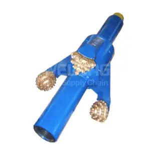
How Does Circulation Rate Affect Hole Opener Cutting Removal and Hole Cleaning?
Moving Large Volumes of Cuttings
When you drill a pilot hole you make a lot less cuttings per foot than when you ream a hole. A hole opener is a device that removes a ring of rock with a big cross-sectional area, and the cuttings have to get out of the cutting zone rapidly. If flow is too low cuttings are reground beneath the cutters. This delays penetration, increases torque and accelerates wear on inserts and bearings.
Annular Velocity in Larger Holes
As the hole becomes larger, the annular velocity will decrease at the same rate at the pumps. This makes for more difficult hole cleaning, particularly in large top-hole portions. Operators of hole openers routinely increase flow rates, alter the mud rheology to increase carrying capacity and regularly pump high viscosity sweeps. In deviated or horizontal holes, pipe rotation also helps to agitate cuttings beds back into the flow stream.
Nozzles and Cutter Cooling
Most of the equipment feature jet nozzles pointed at each cutter. These nozzles wash cuttings away from the bottom of the hole, clean the cutter faces and cool the bearings. A critical aspect of planning for a hole opening run is choosing nozzle diameters that will produce sufficient hydraulic energy at the intended flow rate. Ensure all nozzles are clear and fitted correctly before every run.
Watching Returns at Surface
The returns from the shaker tell how clean the hole is being made. If the cuttings volume suddenly drops, yet the pump pressure or torque increases, it may indicate that cuttings are piling up in the hole. Crews using a hole opener should compare returns with the projected volume for the increased diameter. If the returns are poor they should drill deeper before reaming out the hole.
Hole Opener Torque and Vibration: What Should Operators Monitor During Drilling?
Reading Surface Torque Trends
Torque is a direct mirror of what is occurring at the cutters. “Steady torque increasing with WOB is a sign of healthy cutting. Erratic swings might indicate a change in formation, balling or a cutter that has seized up. Operators should establish torque restrictions below the makeup torque of the string connections and regularly monitor the hole opener when readings are beyond the typical range.
Controlling Stick-Slip and Lateral Vibration
Large tools are particularly susceptible to stick-slip, in which rotation stops and then rapidly releases. They may also experience lateral vibration, or spin, which damages cutters and stabilisers. WOB reduction, RPM change, and stabilisation improvement normally return the hole opener back to smooth spinning. Where available, downhole vibration subs or MWD equipment offer a considerably better picture than surface measurements alone.
Protecting Tool Body and Connections
During expansion, the tool body experiences strong torsional and bending stresses. The excellent hole opener is manufactured from robust alloy steels like AISI 4145H/4145H MOD or AISI 4330V which have been heat treated for strength and impact resistance. Manufacturers that operate under quality systems such as ISO 9001:2015 regulate the uniformity of the material and the machining. But specified operation limits still provide the greatest protection for connections and cutter pockets.
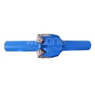
How Can Multi-Pass Hole Opener Drilling Improve Large-Hole Enlargement?
Why Staged Enlargement Works Better
Making one extremely large-diameter hole in a single operation imposes great demands on the cutters and the rig. The multi-pass approach employs a succession of tools, each somewhat bigger than the one before. The hole openers remove a controllable ring of rock which keeps the torque lower and the vibration simpler to regulate and the cuttings quantities are matched to the available pump capacity.
Planning the Pass Sequence
Engineers arrange the plan by formation hardness, rig torque, pump production and eventual target size. For example, a 17 1/2 in. pilot might be expanded to 26 in. and then to 36 in. for conductor casing. The proper size of each hole opener in the sequence is a compromise between duration of drilling vs cutter life, and is sufficient margin so that the casing may be run without difficulties.
Checking Hole Quality Between Passes
Every ball is an opportunity to examine the hole. When the crews extract the tool, they may evaluate cutter wear, conduct callipers or gauge checks, and set parameters for the following phase. If one hole opener is unevenly worn, different stabilisation or rotational speed might be used for the following pass. This step-by-step input considerably enhances the quality of the finished hole and minimises surprises during casing and cementing.
Conclusion
The ideal method to run a hole opener is to think of the run as a planned, supervised operation. Center the tool behind a guided pilot with excellent stabilisation. Work up WOB and RPM progressively to fit formation and cutter type. Maintain enough circulation to handle huge quantities of cuttings; check for torque and vibration carefully, and utilise staged passes for extremely big holes. When used in conjunction with a well-built tool, these techniques help drilling teams drill full-gauge holes, extend bit life and run smoother casing strings.
FAQ
Q1: Should I run a pilot bit or a bull nose ahead of my hole opener?
Use a pilot bit while drilling and then reaming in one operation. If you have a pilot hole and only need something to keep the hole opener centred, use a bull nose.
Q2: Why does a hole opener usually run at lower RPM?
The big diameter translates to a fast tip speed for outer cutters even at modest RPM. A slower rotation preserves bearings and inserts, and helps decrease vibration.
Q3: Which cutter type should I choose?
For soft formations use soft to medium cutters, for mixed intervals use medium to hard cutters and for abrasive or high strength rock use hard formation cutters.
Get a Reliable Hole Opener from WELONG – Contact Our Team Today
China, has over 20 years of expertise in producing oilfield products, Welong produces hole opener tools made from AISI 4145H/4145H MOD and AISI 4330V and cutter kinds for hard, medium-hard and soft-to-medium forms. We are ISO 9001:2015 and API 7-1 Certified. We offer in process and final inspection and may arrange for third party inspection via SGS or DNV. We deliver on time by ship, air or rail on FOB, CIF, DDP or DDU basis and provide bespoke sizes & combinations. Contact us for technical help and rapid quotation: [email protected] now.
References
1. American Petroleum Institute. API Specification 7-1: Specification for Rotary Drill Stem Elements. Washington, DC: API.
2. Bourgoyne, A. T., Millheim, K. K., Chenevert, M. E., & Young, F. S. Applied Drilling Engineering. SPE Textbook Series, Vol. 2. Richardson, TX: Society of Petroleum Engineers, 1986.
3. Mitchell, R. F., & Miska, S. Z. (Eds.). Fundamentals of Drilling Engineering. SPE Textbook Series, Vol. 12. Richardson, TX: Society of Petroleum Engineers, 2011.
4. International Association of Drilling Contractors. IADC Drilling Manual, 12th ed. Houston, TX: IADC.
5. Rabia, H. Well Engineering & Construction. London: Entrac Consulting, 2002.
6. Lyons, W. C., & Plisga, G. J. (Eds.). Standard Handbook of Petroleum and Natural Gas Engineering, 2nd ed. Burlington, MA: Gulf Professional Publishing, 2005.
Share your inquiry, get the quotation accordingly!

CHINA WELONG - 20+ years manufactuer in oilfield tools