How does The Wellhead Equipment Work?
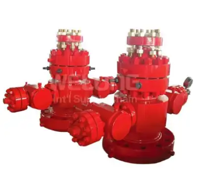
Wellhead equipment is at the top of an oil or gas well. It is the main way that the underground rock talks to the production infrastructure on the surface. It controls pressure, holds downhole strings in place, blocks fluid pathways, and works with safety systems to keep people and the environment safe. To understand how a wellhead works, you have to look at all of its main functions, such as controlling flow and pressure, as well as closing and managing loads. Based on well-known engineering principles and industry standards, this article breaks down these functions in great detail.
How Does a Wellhead Maintain Pressure Control During Drilling and Production?
The Role of the Casing Head in Initial Pressure Containment
The case head is what holds the whole wellhead unit together. It is welded or threaded to the surface casing and holds in place every spool and part that is put on top of it. When drilling, formation pressures can rise for no reason. The case head is the first piece of mechanical support against the forces pushing up. A wellhead that is properly rated must be able to handle working pressures of over 15,000 psi in offshore or high-pressure sources and just a few hundred psi in shallow wells. How well the wellhead system holds pressure over the life of the well depends directly on how well the sealing head is made.
Pressure Rating Systems and Staged Barriers
Following API guidelines, wellhead parts are made and tested to certain pressure classes, which are usually 2,000, 3,000, 5,000, 10,000, and 15,000 psi. Each part of the wellhead stack is rated to meet or beat the expected wellbore pressure at the depth of installation. With this staged method, extra wellhead spools with higher ratings can be added on top of the current unit if the pressure rises as the digging goes deeper. So, the wellhead is not just a static barrier, but a system that controls the pressure that changes over time. This gives operators the freedom to safely drill through several pressure zones in the same wellbore.
Sealing Mechanisms Inside Wellhead Equipment and How They Prevent Fluid Leakage
Metal-to-Metal Seals and Their Advantages Over Elastomeric Alternatives
Metal-to-metal seals are becoming more popular in modern wellhead designs instead of traditional elastomeric (rubber-based) seals. This is especially true in places with high temperatures and pressures. Metal-to-metal seals work by using precisely cut contact surfaces that slightly bend when they are loaded. This makes a leak-proof interface without using a material that can be compressed. This is important because hydrogen sulphide, carbon dioxide, and high temperatures, all of which are common in oil and gas wells, break down elastomers over time. If you have metal-to-metal seals on your wellhead, they will last longer and work better in a wider range of downhole conditions.
Annular Sealing Between Casing Strings
Closing off the space between two adjacent casing strings is one of the most important sealing tasks in any wellhead. As more than one case string is put into a well, they all fit inside the one before them, leaving concentric circular gaps. Formation fluids or gases can move up through the annulus and escape at the wellhead if these holes are not properly covered at the surface. This is a very serious safety risk. The wellhead seals the annulus by using locking screws, packoff systems, and casing hanger seals that squeeze around the outside of each string of casings. These parts work together to make a barrier that keeps each annular zone from touching the air at the surface.
Tubing Hanger Seals in the Production Phase
The tubing hanger hangs the production tubing string from the tubing head spool while it is being made. The tubing hanger has a seal assembly that separates the annulus between the tubing and casing from the flow path for production. This separation is important because it keeps the fluids that are being made from going around the tube and into the opening without being managed. The seal has to work even when hot fluids that are being made flow through the tube, which happens a lot of times. The people who make wellheads make these seals so that they can handle the axial movement that happens because of heat expansion. This keeps the sealing contact even when the length of the tubing string changes during production cycles.
Load-Bearing Function of Wellhead Systems in Supporting Casing and Tubing Strings
How Casing Hangers Distribute Weight Across the Wellhead Stack
Casing strings are extremely heavy. A single string of intermediate casing in a deep well can weigh hundreds of thousands of pounds. The casing hanger — a machined ring that lands inside the casing head or an intermediate spool — transfers this weight from the casing string to the wellhead body and, ultimately, to the surface casing cemented into the ground. This load path must be engineered precisely. If the hanger seats improperly or the landing profile is damaged, the casing string can shift, compromising both the structural integrity of the well and the effectiveness of the annular seals. The wellhead structure is therefore not just a pressure vessel — it is a structural load-bearing frame.
Tubing String Suspension and Axial Load Management
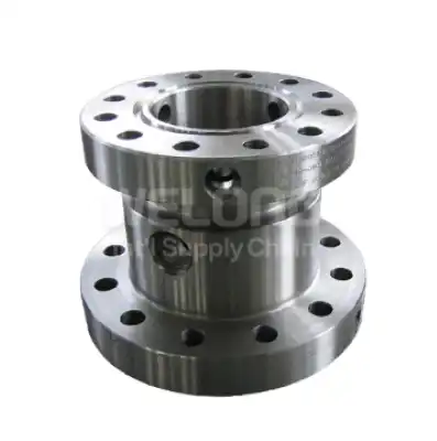
The tubing head spool, which is a component with a top flange and a bottom flange, is installed on the casing head flange to hang tubing strings and to seal the annular space between the tubing and the casing. Beyond simply supporting weight, the tubing hanger system must also manage axial loads generated by pressure acting on the cross-sectional area of the tubing. When wellbore pressure acts upward on the bottom of the tubing string, it generates a significant upward force that the tubing hanger must resist. Wellhead engineers account for this by designing hanger profiles that lock the tubing string in place, preventing it from being pushed upward by pressure surges during production or well interventions.
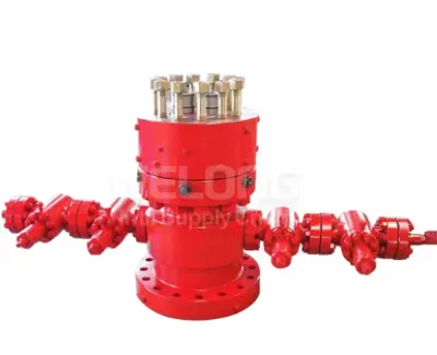
How Flow Path Is Managed and Directed Through a Wellhead Assembly
The Christmas Tree as the Flow Control Interface
The assembly of valves and fittings installed on top of the wellhead — commonly called the Christmas tree — governs how produced fluids move from the wellbore to the surface flow lines. It typically includes a master valve, a wing valve, and a swab valve, each serving a distinct flow control function. The master valve provides primary shut-in capability directly above the tubing hanger. The wing valve directs flow into the production line. The swab valve allows access for wireline or coiled tubing intervention without fully opening the well. Together, these valves give operators precise control over the flow path at every stage of the well's producing life.
Flow Tee and Choke Integration for Pressure Management
Between the Christmas tree and the surface flow line, a flow tee and a choke manifold regulate the pressure and flow rate of produced fluids. The choke restricts flow, creating a pressure drop that allows operators to manage wellbore drawdown — the reduction in reservoir pressure caused by production. Controlling drawdown is critical for protecting reservoir integrity and maximizing long-term recovery. The wellhead assembly provides the mechanical connection points for these downstream pressure management components, integrating them into a unified surface control architecture. This architecture is designed so that each element can be isolated, tested, or replaced independently without shutting in the entire well.
Integration of Wellhead Equipment with Blowout Prevention and Surface Control Systems
Blowout Preventer Stack Connection to the Wellhead
During drilling, a blowout preventer (BOP) stack is bolted directly onto the wellhead. The BOP contains ram preventers and annular preventers that can close around the drill string or seal the wellbore completely in the event of a kick — an uncontrolled influx of formation fluid. The connection between the BOP and the wellhead must be rated to the same pressure class as the BOP itself, ensuring that the wellhead does not become the weak link in the well control system. This integration requires precise flange matching and proper ring gasket sealing at the connection point, both of which are governed by ISO 9001:2015-aligned quality management practices at every stage of manufacture and assembly.
Surface Safety Valves and Emergency Shutdown Integration
These days, emergency shutdown (ESD) panels and surface safety valve (SSV) systems are built into modern wellhead systems. In the flow path after the Christmas tree master valve is a surface safety valve. When sensors find that the pressure, temperature, or flow isn't normal, it closes itself. It only takes seconds for the ESD panel to arrange the shutting down of the whole well with the SSV and other operated valves in the wellhead assembly. With this level of integration, the wellhead goes from being an inactive structure for keeping pressure in check to being an active part of the well's total safety management system. It protects people, tools, and the environment all at the same time by responding to real-time data.
Conclusion
A wellhead is far more than a simple connection point at the top of a well. It manages pressure across multiple rated barriers, seals every annular space between casing and tubing strings, carries enormous structural loads, directs produced fluids through a controlled flow path, and integrates seamlessly with blowout prevention and emergency shutdown systems. Each of these functions depends on precise engineering, certified materials, and rigorous quality control — all of which define what a reliable wellhead system must deliver across its entire service life.
FAQ
Q1: What is the difference between a casing wellhead and a tubing wellhead?
The wellhead assembly is linked to the casing head by a casing wellhead. The wellhead assembly holds the weight of the intermediate and production casing and seals the space between the casing strings. A tubing wellhead, by comparison, is a spool placed on the casing head flange especially to hang the production tubing string and seal the gap between the tubing and the casing during production operations.
Q2: How often should wellhead seals be inspected or replaced?
Wellhead seal inspection frequency depends on well conditions, produced fluid composition, and operating pressures. In high-pressure or sour service wells, seals warrant more frequent inspection. Most operators follow a scheduled inspection program tied to workover cycles or annual well integrity assessments. Metal-to-metal seals generally require replacement less frequently than elastomeric seals, but both types must be evaluated after any significant pressure anomaly or well intervention.
Q3: What pressure ratings are available for wellhead equipment?
API pressure classes of 2,000 psi, 3,000 psi, 5,000 psi, 10,000 psi, and 15,000 psi are used to make wellhead equipment. According to the expected highest surface pressure for that well, the right rating is chosen. To keep the system running properly, operators must make sure that all of the parts in the wellhead stack—the hangers, spools, valves, and seals—are set to at least the same working pressure.
Partner With WELONG for Reliable Wellhead Equipment Solutions
When performance and compliance matter, WELONG delivers. Founded in 2001 and certified to both ISO 9001:2015 and API 7-1, WELONG has spent over two decades supplying high-quality oilfield equipment to international markets. Our casing and tubing wellhead products undergo stringent in-process and final inspection, with third-party inspection through SGS and DNV available on request. We offer flexible shipping — sea, air, and rail — and support multiple trade terms including FOB, CIF, DDP, and DDU. If you are sourcing dependable wellhead equipment backed by proven quality control, contact our team directly at [email protected].
References
1. Adams, N. J., & Charrier, T. (1985). Drilling Engineering: A Complete Well Planning Handbook. PennWell Publishing.
2. Bourgoyne, A. T., Millheim, K. K., Chenevert, M. E., & Young, F. S. (1986). Applied Drilling Engineering. Society of Petroleum Engineers Textbook Series, Vol. 2.
3. American Petroleum Institute. (2015). API Specification 6A: Specification for Wellhead and Christmas Tree Equipment (21st ed.). API Publishing Services.
4. Skalle, P. (2012). Pressure Control During Oil Well Drilling. Bookboon Engineering & Energy.
5. Mitchell, R. F., & Miska, S. Z. (Eds.). (2011). Fundamentals of Drilling Engineering. Society of Petroleum Engineers Monograph Series, Vol. 12.
6. Gabolde, G., & Nguyen, J. P. (2006). Drilling Data Handbook (8th ed.). Editions Technip.
Share your inquiry, get the quotation accordingly!

CHINA WELONG - 20+ years manufactuer in oilfield tools