What Is a Kill Manifold? Uses, Benefits, and Key Specs
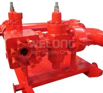
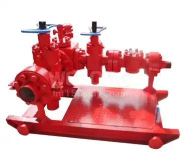
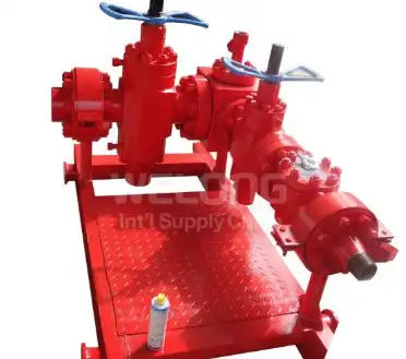
The kill manifold is the equipment that allows drilling teams a method to fight back if wellhead pressure begins to rise and a kick threatens to turn into something much more serious. Built from gate valves, check valves, line pipes, and pressure gauges, this high-pressure system offers a dedicated path for putting heavy drilling fluid into the well to restore bottomhole pressure balance and securely vent increasing pressure when circumstances require it. The death manifold is a little box with a great duty. Rated from 2,000 to 20,000 psi and constructed to API SPEC 16C, this guide describes the components, the function of the well control, main applications, and requirements to check before ordering.
What Are the Main Components of a Kill Manifold and How Do They Work?
Gate Valves: The Primary Flow Control
Gate valves are the heart of any kill manifold, opening and shutting to provide the flow channels that guide kill fluid to the well. These are not your everyday pipeline valves; they are pressure-rated, metal-sealed valves for abrasive drilling mud and quick operation at full differential pressure. In series throughout the manifold, they offer redundant isolation, such that one valve may be closed as a working barrier, with another as backup. Years of high-pressure cycling won’t affect their rugged bodies and seats or shutdown integrity.
Check Valves for One-Way Protection
The check valve is the kill manifold's silent guardian against backflow. Positioned on the pump side of the assembly, it allows heavy mud to flow toward the well while automatically preventing well fluids from reversing back toward the pumps and surface equipment. During a kill operation, when pump pressure and well pressure fluctuate against each other, this one-way protection keeps the pumping system isolated from sudden pressure surges. A reliable check valve means crews can stage pumps confidently, knowing the manifold itself stands between them and the well.
Line Pipes and Pressure Gauges
High-pressure line pipes tie the kill manifold together, carrying kill fluid from the pumps to the wellhead connection at full rated pressure. Their bore sizes—typically 2-1/16" to 4-1/16"—are selected to deliver adequate flow rates without excessive friction loss during critical pumping. Pressure gauges mounted on the manifold give the crew continuous visibility of pump pressure and wellhead response, turning the kill manifold into a monitoring station as well as a flow path. Accurate readings here guide every decision made during a well kill.
How Does a Kill Manifold Support Well Control During Drilling Operations?
Pumping Heavy Fluid to Regain Balance
The defining mission of a kill manifold is delivering kill-weight mud into the wellbore. When formation pressure exceeds the hydrostatic column—a kick—the crew engages the manifold, opens its gate valves in sequence, and pumps weighted fluid down the annulus or drill string until bottomhole pressure is balanced again. Because this operation may run for hours at thousands of psi, every component in the kill manifold must hold its rating flawlessly from the first barrel to the last, restoring control methodically rather than through desperate measures.
Venting Pressure Through Blowdown Lines
Sometimes the correct response is release rather than injection. Connected blowdown lines allow the kill manifold to vent rising wellhead pressure directly to a safe disposal area, relieving stress on the casing, wellhead, and BOP stack while the crew plans its next move. This controlled depressurization prevents pressure from building to dangerous levels at the surface. The manifold's valves meter the release carefully, because dumping pressure too quickly can be as hazardous as holding it—precision is the entire point of the system.
Emergency Injection of Water and Extinguishing Agents
Beyond mud and pressure relief, the kill manifold serves as an emergency injection pathway in worst-case scenarios. Water or extinguishing agents can be pumped into the well through the manifold to cool downhole conditions and suppress fire risk when well control events escalate. This versatility means the kill manifold earns its place on location even when it is never called upon—it functions as pre-positioned emergency infrastructure, ready to deliver whatever fluid the situation demands through a single, permanently installed connection.
Key Applications of Kill Manifold in Oilfield Drilling and Well Service
Land Rigs and High-Pressure Gas Drilling
Onshore drilling—especially in deep gas formations where kicks develop fast and violently—relies on a properly sized kill manifold standing ready beside the BOP stack. Land rigs value skid-mounted configurations that rig up quickly and move between locations with the rest of the well control package. With working pressures spanning 2,000 to 20,000 psi, one manifold family can serve everything from shallow development wells to high-pressure exploration targets, giving drilling contractors fleet-wide standardization on a single, proven design.
Offshore Platforms and Floating Operations
Offshore, the kill manifold integrates into a tightly orchestrated well control system where space is scarce and response must be immediate. Platform installations hard-pipe the manifold between the mud pumps and the BOP, with valve positions marked and rehearsed so any crew member can line up a kill in the dark. Temperature class LU construction, rated from -46°C to 121°C, suits cold-climate offshore basins, while corrosion-resistant materials endure the salt-laden atmosphere that attacks ordinary equipment throughout a long platform deployment.
Workover, Snubbing, and Well Intervention
Well service operations face live-well conditions by definition, making the kill manifold indispensable during workovers, completions, and snubbing jobs. Before pulling tubing or swabbing, crews may need to bullhead kill fluid into the well to stabilize it; during intervention, the manifold remains lined up as an instant-response tool against unexpected pressure. Its compact footprint suits the smaller spreads of service rigs, and its simple valve logic means intervention crews—who may see a different well every week—can operate it confidently without specialized retraining.
What Technical Specifications Should Buyers Check When Selecting a Kill Manifold?
Working Pressure and Nominal Bore
Start with the well itself: the kill manifold's working pressure must meet or exceed the maximum anticipated surface pressure of your drilling program, with ratings available from 2,000 psi through 20,000 psi. Nominal bore—ranging from 2-1/16" to 4-1/16"—determines achievable pump rates, so match it to your mud pump capacity and the kill volumes your well plan requires. Under-sizing the bore creates friction losses that slow a kill precisely when speed matters, so treat flow capacity as seriously as pressure rating.
Material Class and Working Temperature
Fluid environment dictates metallurgy. Kill manifold assemblies in material classes EE and FF handle sour service containing H₂S and CO₂, with corrosion-resistant alloys protecting valve internals, seal areas, and line pipe bores. Buyers can consult material performance data from the National Science Data Center for Corrosion and Protection of Materials when comparing options for specific fluid compositions. Confirm temperature class LU (-46°C to 121°C) for cold-region operations, and provide your supplier with a full fluid analysis so material selection matches reality rather than assumption.
API SPEC 16C Compliance and Testing Documentation
API SPEC 16C is the governing standard for choke and kill equipment, covering design, materials, manufacture, and testing. A compliant kill manifold arrives with documented hydrostatic pressure tests, material traceability records, and dimensional verification for every valve and connection. Buyers should also examine the manufacturer's quality system—ISO 9001:2015 and API 7-1 certification signal audited, repeatable processes. Suppliers like WELONG add further assurance through in-process and final inspection, with optional SGS or DNV third-party verification for projects demanding independent confirmation.
Valve Configuration and Layout Flexibility
No two rigs arrange their well control spread identically, so layout matters. Discuss valve count and arrangement, inlet and outlet connection types, gauge positions, and skid dimensions with your supplier before ordering. An experienced manufacturer can customize the kill manifold to line up with your existing BOP connections, pump positions, and deck constraints—eliminating field modification and the delays that come with it. This is where suppliers with genuine engineering capability, rather than catalog-only traders, demonstrate their value to your operation.
How Does a Kill Manifold Improve Pressure Management and Operational Performance?
Faster, More Controlled Response to Pressure Events
Well control is a race, and a permanently installed kill manifold removes setup from the critical path. The moment rising pressure is confirmed, the crew lines up pre-positioned valves and begins pumping—no hunting for fittings, no rigging up temporary lines under stress. Practiced crews execute this in minutes. Over a drilling program, that readiness converts potential blowouts into routine well kills, protecting personnel, the reservoir, and the substantial capital invested in the well itself. Preparedness is the manifold's core contribution to performance.
Redundancy That Keeps Operations Moving
Series-mounted gate valves give the kill manifold built-in redundancy: working valves handle routine duty while backup valves stand ready if the primary set needs service. This arrangement allows valve maintenance without taking the well control system offline—a significant operational advantage on long drilling campaigns. Combined with the check valve's automatic backflow protection, the manifold maintains full readiness through the wear and tear of real drilling, ensuring that the safety system is never the reason a rig has to stop and wait.
Long-Term Reliability With Minimal Upkeep
A well-built kill manifold asks little and delivers much. With no rotating equipment and few elastomers exposed to flow, maintenance concentrates on periodic valve greasing, gauge calibration, and pressure testing per the operator's well control policy. High-strength, corrosion-resistant construction in classes EE and FF extends service life across multiple rigs and decades of standby-plus-intermittent-duty cycles. For asset managers, this translates into a safety-critical system with an exceptionally low lifetime cost—equipment you inspect regularly but seldom need to repair or replace.
Conclusion
The kill manifold may spend much of its existence standing mute by the BOP, but as wellhead pressure increases, it becomes the most crucial assembly on site. It employs gate valves, check valves, line pipes and gauges to pump heavy mud to restore balance, to release pressure safely via blowdown lines and to pump in emergency fluids should things get out of control. Buyers have a well control asset that will be ready for decades by matching operating pressure, bore size, material class, and API 16C compliance to well circumstances and sourcing from approved manufacturers. In drilling, preparation is key, and the kill manifold is just that.
FAQ
Q1: What is the difference between a kill manifold and a choke manifold?
The kill manifold pumps fluid into the well to restore bottomhole pressure balance during a kick, while the choke manifold controls the release of fluid and gas out of the well, maintaining backpressure during circulation. The two work as a paired system: the kill manifold manages inflow, the choke manifold manages outflow, and together they execute a controlled well kill.
Q2: What working pressure should I choose for a kill manifold?
Select a rating that meets or exceeds your maximum anticipated surface pressure—typically matching your BOP stack rating. Standard options range from 2,000 psi to 20,000 psi. Also verify that every component, including gate valves, check valves, and line pipes, carries the same rating, and confirm the nominal bore (2-1/16" to 4-1/16") supports your required kill pump rates.
Q3: What does API SPEC 16C compliance cover?
API SPEC 16C is the international standard for choke and kill equipment, governing design, materials, manufacturing, welding, and testing. Compliance ensures the kill manifold's pressure-containing components are verified through documented hydrostatic testing, that materials are traceable, and that connections and dimensions meet globally recognized requirements for safe integration into well control systems.
Strengthen Your Well Control System With WELONG
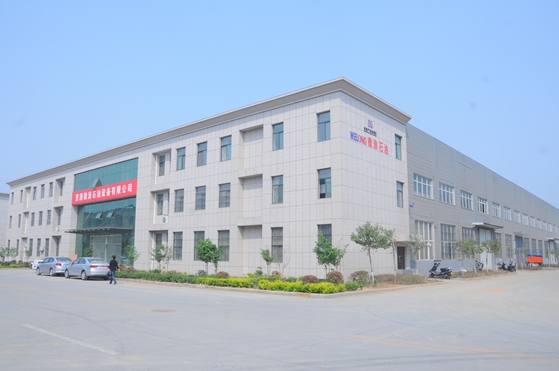
Need a kill manifold built to perform when it matters most? Founded in 2001, China WELONG is a professional international supply chain service provider specializing in oilfield products and customized solutions, certified to ISO 9001:2015 and API 7-1. Our API SPEC 16C-compliant kill manifolds cover 2,000–20,000 psi working pressures, nominal bores from 2-1/16" to 4-1/16", and material classes EE and FF—all manufactured under strict quality control with SGS and DNV third-party inspection available. With flexible sea, air, and railway transport and terms from FOB to DDP, we deliver on schedule, worldwide. Contact our team today at [email protected] for a tailored quotation and expert technical support.
References
1. American Petroleum Institute. API Specification 16C: Choke and Kill Equipment, 2nd Edition. API Publishing, 2015.
2. American Petroleum Institute. API Recommended Practice 53: Blowout Prevention Systems for Drilling Wells, 4th Edition. API Publishing, 2012.
3. Grace, Robert D. Blowout and Well Control Handbook, 2nd Edition. Gulf Professional Publishing, 2017.
4. Watson, David, Terry Brittenham, and Preston L. Moore. Advanced Well Control. Society of Petroleum Engineers, 2003.
5. International Association of Drilling Contractors. IADC Deepwater Well Control Guidelines, 2nd Edition. IADC, 2015.
6. Lyons, William C., and Gary J. Plisga. Standard Handbook of Petroleum and Natural Gas Engineering, 2nd Edition. Gulf Professional Publishing, 2005.
Share your inquiry, get the quotation accordingly!
CHINA WELONG - 20+ years manufactuer in oilfield tools