Choke Manifold vs Kill Manifold: Key Differences for Buyers
Any drilling rig you stand on, you'll see two high-pressure manifolds on either side of the BOP stack that look sufficiently alike that beginners are prone to confusing them. But the choke manifold and the kill manifold do the opposing parts of the same life-saving action; one controls what flows out of the well and the other what is pumped in. This collaboration is vital for purchasers selecting well control equipment to understand—choosing the incorrect design, pressure rating, or valve arrangement jeopardises the whole well control system. This tutorial covers the fundamental distinctions between the choke manifold and its kill-side equivalent, contrasts their responsibilities in pressure and fluid control, and shows how to specify both with certainty for your drilling program.
What Is the Difference Between Choke Manifold and Kill Manifold in Well Control Systems?
Flow Direction: Outflow vs Inflow
The basic distinction is direction. A choke manifold handles fluids from the well – gas, mud and formation fluids – which are expelled via adjustable choke valves that provide exact backpressure on the annulus. The kill manifold performs the opposite, giving a dedicated channel to pump heavy muck into the well. The choke manifold is connected to one side of the BOP spool flange so that when the BOP shuts, the choke valve opening is adjusted to manage the casing pressure and maintain balanced conditions at the bottomhole for the whole circulation.
Core Components and Valve Types
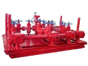
Both assemblies share gate valves, line pipes, fittings, and pressure gauges, but their defining components differ. The choke manifold is built around its choke valves—adjustable or positive chokes, available with manual or hydraulic actuators—that throttle flow continuously under erosive, high-velocity conditions. The kill manifold instead centers on check valves that guarantee one-way flow toward the well, protecting pumps from backflow. This component distinction reflects each unit's purpose: throttling outflow versus safeguarding inflow during critical well control operations.
Position and Connection in the Stack
Physical placement mirrors function. The choke manifold connects downstream of the BOP's annular outlet, routing returns toward the mud-gas separator and flare lines. The kill manifold ties into the BOP or wellhead on the pump side, linking mud pumps to the wellbore. Because both connect directly to the pressure-containing stack, each must match the BOP's working pressure and flange specifications exactly—there is no room for mismatched ratings at these critical interfaces in the well control system.
How Do Choke Manifold and Kill Manifold Perform Different Functions During Drilling Operations?
The Choke Manifold's Role in Circulating Out a Kick
When a kick is shut in, the choke manifold becomes the crew's primary instrument for regaining control. As kill-weight mud circulates, the choke operator adjusts valve opening to hold casing pressure on target, ensuring bottomhole pressure stays slightly above formation pressure without fracturing the zone. This delicate balancing act continues for hours until the influx is fully circulated out. The choke manifold makes the entire driller's method possible—without precise, responsive throttling, a controlled well kill simply cannot happen.
The Kill Manifold's Role in Restoring Hydrostatic Balance
While the choke manages outflow, the kill manifold delivers the remedy. It routes heavy drilling fluid from the mud pumps into the wellbore, rebuilding the hydrostatic column that the kick compromised. Its check valves stand guard against reverse flow as pump pressure and well pressure battle each other, while its gate valves line up the flow path in a practiced sequence. In bullheading operations, the kill manifold also pumps influx fluids back into the formation when circulation through the choke is not feasible.
Supporting Managed Pressure and Balanced Drilling
Beyond emergencies, the choke manifold enables modern drilling techniques outright. Balanced and managed pressure drilling rely on adjusting choke opening to control annular pressure within a narrow window, minimizing pressure differential at the formation face. This capability avoids oil-layer contamination, improves drilling speed, and controls blowout risk proactively. The kill manifold supports these operations as the standby injection path, but it is the choke manifold's continuous, fine-grained pressure regulation that makes precision drilling techniques work day after day.
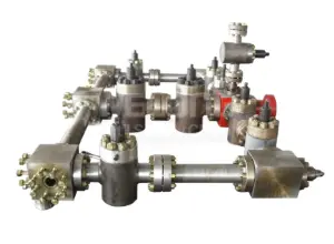
Choke Manifold vs Kill Manifold: Comparing Pressure Control and Fluid Management Roles
Continuous Throttling vs Direct Pumping
Pressure control style separates the two manifolds sharply. The choke manifold exerts control continuously, its valves constantly trimmed to hold target backpressure as fluid volumes, gas fractions, and flow rates change minute by minute. The kill manifold controls pressure through pumping—its contribution is delivering fluid volume and pressure on demand rather than modulating flow. Buyers should recognize this distinction when evaluating valve automation: hydraulically actuated chokes with remote control panels suit the choke manifold's dynamic duty perfectly.
Handling Erosive, Gas-Cutting Returns
The fluids each manifold handles also differ in character. A choke manifold must survive the worst the well can produce: high-velocity, gas-cutting, solids-laden returns that attack valve trims relentlessly during a kill. Hardened choke trims, erosion-resistant bodies, and replaceable wear components define quality here. The kill manifold handles clean, weighted mud from the pits—abrasive but predictable—so its design priorities center on pressure integrity and reliable check valve action rather than extreme erosion resistance.
Instrumentation and Monitoring Requirements
Both manifolds carry pressure gauges, but the choke manifold demands richer instrumentation because it is operated actively. Casing pressure, choke position, flow rates, and cumulative returns all feed the well control decision process, often displayed at a remote choke control panel—universal-function LCPs tested and delivered with the manifold streamline this integration. The kill manifold's monitoring needs are simpler: pump pressure and wellhead response suffice. Specifying instrumentation matched to each role avoids both gaps and unnecessary cost.
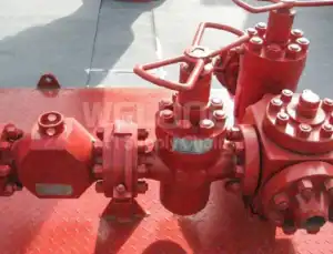
Which Well Conditions Require a Choke Manifold Instead of a Kill Manifold?
High-Pressure Gas Wells With Kick Risk
Deep gas wells, where influxes arrive fast and expand violently during circulation, make the choke manifold absolutely indispensable. Only precise backpressure control can manage gas expansion safely as the influx travels up the annulus, preventing dangerous pressure spikes at surface. These wells justify premium specifications: working pressures to 15,000 or 20,000 psi, hydraulic actuation for remote operation, and dual-choke arrangements that keep the system online even if one choke needs attention mid-circulation.
Narrow Margin and Depleted Formations
Wells drilled through depleted zones or narrow pressure windows face a constant tightrope between kick and lost circulation. Here the choke manifold's fine pressure adjustment is the enabling technology, holding annular pressure within margins sometimes measured in fractions of a specific gravity unit. Managed pressure drilling systems build entire automated control loops around the choke manifold for exactly this reason. The kill manifold remains essential backup, but daily pressure management belongs to the choke side.
Sour Service and Corrosive Environments
Wells producing H₂S or CO₂ demand that every pressure-containing component resist sulfide stress cracking, and the choke manifold answers with NACE MR-0175-compliant materials across valves, chokes, and line pipes. Buyers can benchmark material selections against resources such as ASTM International standards when reviewing manufacturer specifications for sour service trims and bodies. Because sour kicks are doubly hazardous—pressure plus toxicity—the choke manifold's reliable, remotely operated control becomes a genuine lifesaving system.
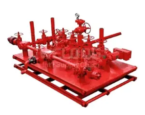
Understanding How Choke Manifold and Kill Manifold Work Together in Oilfield Operations
The Paired System Behind Every Well Kill
A successful well kill is a duet, not a solo. The kill manifold pumps weighted mud in; the choke manifold meters displaced fluid and gas out; together they execute the pressure choreography that restores control. Neither can substitute for the other—pumping without controlled outflow would fracture the formation, while choking without kill fluid supply simply delays the inevitable. Buyers should therefore specify both manifolds as a coordinated package, with matched pressure ratings and connection standards such as API Spec 16C and API Spec 6A.
Layout, Footprint, and Rig Integration
Practical integration deserves early attention. Modern choke manifold designs offer reduced weight and footprint to allow standard freight options, with fixed base or lifting base configurations that suit different rig floors. Hydraulically actuated components allow remote operation from a safe distance, an important layout consideration on compact offshore decks. Coordinating the placement of both manifolds—choke line routed to the separator, kill line tied to the pumps—during rig design prevents costly field modification and speeds rig-up on every location.
Unified Quality Assurance for Both Units
Because the choke manifold and kill manifold share the same criticality, they deserve the same procurement rigor. Insist on API Spec 16C compliance, NACE MR-0175 for sour service, complete pressure test documentation, and material traceability for both assemblies. Manufacturers certified to ISO 9001:2015 and API 7-1, such as WELONG, apply audited quality systems across their entire manifold range and offer SGS or DNV third-party inspection—giving buyers a single, accountable source for the complete well control package.
Training and Operational Readiness
Equipment only performs when crews know it intimately. Because the choke manifold is operated actively during well control events, choke handling and remote panel operation should feature prominently in well control training, while kill manifold lineup procedures should be drilled until automatic. Standardizing both manifolds across a fleet amplifies training value—crews moving between rigs encounter identical valve logic, identical panels, and identical response procedures, eliminating the hesitation that unfamiliar equipment causes when seconds count.
Conclusion
The choke manifold and kill manifold are complementary halves of one system: the choke controls outflow with continuous, precise backpressure, while the kill manifold delivers weighted fluid inward to restore balance. Their differences—in flow direction, valve technology, erosion exposure, and instrumentation—dictate distinct specification priorities, yet their shared criticality demands identical quality standards. Buyers who understand these roles, match ratings and materials to well conditions, and source both units as a coordinated API 16C-compliant package build well control systems that perform flawlessly when pressure rises. Choose both wisely, and drill with confidence.
FAQ
Q1: Can a choke manifold be used as a kill manifold in an emergency?
While both connect to the BOP stack, they are engineered for opposite duties—the choke manifold throttles erosive outflow, while the kill manifold's check valves protect pumps during injection. Substituting one for the other compromises safety and equipment integrity. Best practice is maintaining both units, fully rated and inspected, so each performs its designed function when well control events occur.
Q2: What standards should a choke manifold comply with?
A quality choke manifold should meet API Spec 16C for choke and kill equipment, API Spec 6A for wellhead components, and NACE MR-0175 for sour service where H₂S is present. Buyers should also request hydrostatic test certificates, material traceability records, and documentation for manual or hydraulic actuator options, plus confirmation that control panels are function-tested with the manifold before delivery.
Q3: Should I choose manual or hydraulic choke valves?
Manual chokes suit simpler land operations where the operator can work safely at the manifold. Hydraulic actuation enables remote operation from a control panel, keeping personnel away from high-pressure lines during kicks—strongly recommended for high-pressure gas wells, offshore installations, and sour service. Many buyers specify dual configurations, gaining remote precision with manual backup for maximum operational resilience.
Complete Your Well Control Package With WELONG
Need a choke manifold and kill manifold engineered to work as one system? Founded in 2001, China WELONG is a professional international supply chain service provider specializing in oilfield products and customized solutions, certified to ISO 9001:2015 and API 7-1. Our choke manifolds meet API Spec 6A, API Spec 16C, and NACE MR-0175, with manual and hydraulic actuation, reduced-weight footprints, fixed or lifting bases, and LCPs tested and delivered with each unit—all backed by SGS and DNV third-party inspection options. With sea, air, and railway transport and terms from FOB to DDP, we deliver on schedule, worldwide. Contact us today at oiltools@welongpost.com for a tailored quotation and expert support.
References
1. American Petroleum Institute. API Specification 16C: Choke and Kill Equipment, 2nd Edition. API Publishing, 2015.
2. American Petroleum Institute. API Recommended Practice 53: Blowout Prevention Systems for Drilling Wells, 4th Edition. API Publishing, 2012.
3. Grace, Robert D. Blowout and Well Control Handbook, 2nd Edition. Gulf Professional Publishing, 2017.
4. Watson, David, Terry Brittenham, and Preston L. Moore. Advanced Well Control. Society of Petroleum Engineers, 2003.
5. International Association of Drilling Contractors. IADC Deepwater Well Control Guidelines, 2nd Edition. IADC, 2015.
6. Lyons, William C., and Gary J. Plisga. Standard Handbook of Petroleum and Natural Gas Engineering, 2nd Edition. Gulf Professional Publishing, 2005.
Share your inquiry, get the quotation accordingly!

CHINA WELONG - 20+ years manufactuer in oilfield tools