Sleeve Stabilizer for Oilfield Drilling: A Practical Guide
A sleeve stabilizer is a component of the BHA intended to sustain wellbore contact and aid control the drillstring movement. Nominal size is not the only factor affecting its performance. Other factors include sleeve and blade design, gauge, location, material and drilling conditions. This practical guide discusses how to analyse those aspects when choosing a sleeve stabiliser for vertical, directional and deviation-control drilling, and details what to negotiate with a supplier in specifying a replacement design.
What Role Does a Sleeve Stabilizer Play in the Bottom Hole Assembly?
Stabilizing the BHA and Managing Lateral Movement
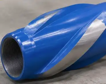
A sleeve stabiliser is a bottom-hole assembly (BHA) component that offers a regulated, near-gauge contact surface against the wellbore. The BHA sits between other drillstring equipment and helps minimise lateral movement to support the bit’s planned route while the assembly spins. Its contribution varies on sleeve geometry, gauge and location in the BHA and hence it has to be chosen as a part of the overall drilling assembly and not as an independent component.
Supporting Bit Direction and Assembly Behavior
During drilling, the BHA reacts to forces created at the bit and along the drill string. A sleeve stabiliser provides engineers with points of contact to design the behaviour of the assembly in the hole. The reaction relies on the location of the stabiliser in respect to the bit, collars, motor or other equipment. When looked at as one, teams may choose a setting that corresponds to their trajectory goal.
Working with Other BHA Components
A sleeve stabiliser operates in tandem with the other tools in the BHA, not in substitute of them. Its size and spacing may impact how the assembly reacts with the wellbore while the bit and directional tools go about their business. Engineers should validate connection details, BHA arrangement, hole size and the anticipated operating envelope before purchase. The synchronised review gives the drilling crew additional helpful information on the stabiliser specification.
Sleeve Stabilizer Blade and Sleeve Design: Key Parts of the Stabilizing System
Replaceable Sleeve and Integral Mandrel
WELONG interchangeable sleeve stabiliser has a mandrel integrated and sleeve separate. You might have a mandrel series with sleeves of varying diameters for different hole sizes when designing equipment for separate parts. When selecting a sleeve stabiliser, ensure that the series and connection of the mandrel, the dimensions of the sleeve and the BHA are compatible with the setup and the task requirements.
Blade Geometry and Contact Pattern
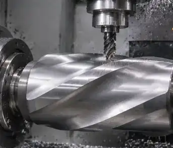
The sleeve stabilizer shape and contact pattern may assist determine how a sleeve stabiliser interacts the wellbore. The blade width, dispersion and overall geometry should be examined in relation to the hole size and the stabilisation purpose of the BHA. Because available designs may vary, engineers should check the supplier’s drawings and dimensions information rather than presume that all sleeves have the same profile. That little bit of info is very valuable when trying to match a new sleeve to a mandrel already in existence.
Material and Hardfacing Options
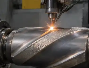
WELONG sleeve stabiliser options include AISI 4145H, AISI 4145H MOD and nonmagnetic. The hardfacing alternatives include HF1000, HF2000, HF3000, HF4000 and HF5000.The proper choice is based on the application and the product requirements of the provider. Teams may refer to appropriate ASTM International standards when establishing material tests or documentation and agree with the supplier on which requirements will apply to the component.
How Does Sleeve Stabilizer Gauge Affect Wellbore Contact and Hole Size?
Gauge as the Working Contact Dimension
The gauge of a sleeve stabiliser is the outer dimension at the contact surfaces and is a significant feature of its fit with the desired hole . This helps engineers predict how the sleeve will meet the wellbore, and how the BHA will be supported. For comparison you may verify the supplier’s stated gauge, hole size, sleeve drawing and measuring technique employed.
Matching Gauge to the Planned Hole Size
The first step in choosing a sleeve stabiliser gauge is the intended hole size of the section and the BHA design that is needed. The dimension selected should be according to the requirements of the project and the function of the stabiliser in the assembly. When one series of mandrels is used with several sleeves, check the size and identity of each sleeve before using. Labelling and dimensions data are clear to enable the team match the proper component to each hole segment.
Checking Sleeve Dimensions and Replacement Fit
The sleeve size is a different consideration from the mandrel as the design is removable but the specifications and compatibility need to be validated. Before running a sleeve stabiliser inspection teams may verify its gauge, sleeve condition, connection details and records against the purchase specification. Recording these information also helps with future replacement planning, especially if you want to use the same mandrel series for more than one hole size.
Sleeve Stabilizer Placement in Vertical, Directional, and Deviation Control Drilling
Vertical Wells: Designing for a Stable BHA
The sleeve stabiliser is designed in a vertical part to accommodate the anticipated BHA reaction and to assist keep the well on the desired course. The number and spacing of the stabilisers is a function of the overall assembly, bit size, hole size and drilling program. Instead of choosing a sleeve stabiliser based on gauge alone, engineers should consider where it fits in the BHA and verify that the preferred arrangement is appropriate for the vertical-well purpose.
Directional Sections: Coordinating with the BHA
of directional drilling, the sleeve stabiliser is a component of a system that may contain a motor, rotary steerable system, bent housing and other bottom-hole assembly components. The location and gauge may be taken into account when designing how the assembly reacts when constructing, holding or changing inclination. The required reaction differs for each segment therefore the drilling crew has to check the stabiliser spacing and tool compliance with the directional plan.
Deviation Control: Matching Placement to the Objective
Engineers examine the sleeve stabilizer's position relative to the bit and other contact points while controlling deviation. This positioning together with the stabilizer’s gauge and the remainder of the BHA design contributes to shaping the assembly’s reaction to the wellbore. The practical review include the goal trajectory, anticipated hole size, tool arrangement and expected operation circumstances. Final placement should be in accordance with the drilling program and suggestions of the BHA designer.
How Do Drilling Conditions Influence Sleeve Stabilizer Selection and Performance?
Formation, Weight on Bit, and Rotary Speed
The sleeve stabiliser standard is based on formation type and operating factors. When the drilling team evaluates sleeve material and hardfacing possibilities, they might consider projected rock properties, weight on bit, rotary speed, and the anticipated service for the BHA. These considerations assist in framing a product conversation with the provider and advise the selection of a configuration appropriate to the job. The final decision should be verified against the defined boundaries of the instrument.
Drilling Fluid and Magnetic Requirements
Downhole temperature, fluid characteristics and the presence of abrasive materials are all helpful inputs to the choice of sleeve stabiliser material and surface option. The non-magnetic configuration may be set as needed by the measurement-tool design in assemblies next to magnetic survey equipment. Sharing such circumstances with the supplier allows for the development of a proper specification and inspection plan, including any material or dimensional requirements the project has.
Inspection, Documentation, and Delivery
An order for a full sleeve stabiliser should include dimensions, materials, hardfacing, inspection points, and delivery requirements. WELONG says it is ISO 9001:2015- and API 7-1-certified. In-process and final inspection is available; third-party inspection may also be performed with companies like as SGS or DNV. Early confirmation of paperwork and logistics also helps ensure the product arrives to the customer’s warehouse according to the project timeline.
Conclusion
When choosing a sleeve stabilizer, align the sleeve stabiliser design, gauge, material and BHA location to the well plan and drilling environment. The mandrel series may be supported with a replacement sleeve arrangement for varied hole sizes. Material and hard facing variations enable points for application specific customisation. Good orders need good designs, dimensional verification, delivery planning and inspection records. Discussing these aspects with an experienced provider allows drilling teams to design a sleeve stabiliser that meets their assembly requirements and operational goals.
FAQ
1. What is the main function of a sleeve stabilizer?
It creates a regulated contact point in the BHA to assist control lateral movement and support the behaviour of the assembly in the wellbore as planned. Its function is dependent on its gauge, location, design and connection to other BHA components.
2. Can one mandrel series be used with sleeves for different hole sizes?
Yes. The interchangeable design of WELONG enables a succession of mandrels to be mounted with sleeves of varied diameters. Confirm sleeve dimensions and compatibility with the given mandrel and BHA before purchase.
3. What material and hardfacing options are available?
Materials include AISI 4145H, AISI 4145H MOD and nonmagnetic versions. Hardfacing choices range from HF1000 to HF5000. Request supplier to confirm viable alternatives for application and relevant paperwork
Request a Sleeve Stabilizer Quote from WELONG
Need a sleeve stabilizer for a certain hole size or BHA? WELONG of China has been in the oilfield supply business since 2001 and provides unique product support, material choices and hardfacing alternatives. Tell our experts your hole size, mandrel needs, drilling circumstances and intended delivery date. We may discuss in-process and final inspection, as well as third party inspection arrangements via SGS or DNV. Sea, Air and Railroad alternatives and Terms like FOB, CIF, DDP, DDU available. For Specifications, Inspection plan or Quotation, contact [email protected].
Selected References
1. Bourgoyne, A. T. Jr., et al. Applied Drilling Engineering. SPE Textbook Series, Vol. 2. Society of Petroleum Engineers, 1986.
2. Mitchell, R. F., and S. Z. Miska. Fundamentals of Drilling Engineering. SPE Textbook Series, Vol. 12. Society of Petroleum Engineers, 2011.
3. Rabia, H. Oilwell Drilling Engineering: Principles and Practice. Graham & Trotman, 1985.
4. Aadnoy, B. S., et al. Advanced Drilling and Well Technology. Society of Petroleum Engineers, 2009.
5. American Petroleum Institute. API Specification 7-1: Rotary Drill Stem Elements. 2nd ed., 2016.
6. Moore, P. L. Drilling Practices Manual. 2nd ed. PennWell Books, 1986.
Share your inquiry, get the quotation accordingly!

CHINA WELONG - 20+ years manufactuer in oilfield tools